Power Electronics Full Wave Rectifier
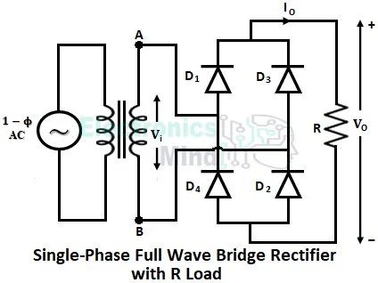
We can see the effect it has on the rectified output waveform with different values of smoothing capacitor installed. The concept of the full wave rectifier is that it utilises both halves of the waveform to provide an output and this greatly improves its efficiency A full wave rectifier is defined as a type of rectifier that converts both halves of each cycle of an alternating wave (ac signal) into a pulsating dc signal
What is Full Wave Rectifier ? - Circuit Diagram, Working, Advantages
Complete guide to full wave rectifier We have created dedicated articles for both types of full wave rectifiers, where we discussed their definitions, circuit diagrams, working principles, output waveforms. Learn working principle, circuit types, formulas, waveform, advantages, and comparison with half wave rectifier.

Full Wave Rectifier : Circuit Diagram, Types, Working & Its Applications

22 Full Wave Rectifier with smoothing Capacitor (Electronic Tutorial
Rectifier
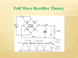
Full Wave Rectifier
What is Full Wave Rectifier ? - Circuit Diagram, Working, Advantages

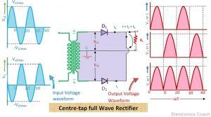
Full Wave Rectifier Waveform Full Wave Rectifier All Formulas With

Full Wave Rectifier Waveform

Full Wave Rectifier Basics, Circuit, Working & Applications

Full Wave Rectifier : Circuit Diagram, Types, Working & Its Applications
Full Wave Rectifier Circuit | PPTX