Zero Suppression And Zero Elevation Calculations & Youtube
Zero suppression and zero elevation explained with calculator a complete guide to calculating lrv, urv and span for differential pressure level. Zero suppression and zero elevation calculation zero suppression and zero elevation calculations inst tools is the #1 website for instrumentation, plc, dcs, and control systems worldwide. Without proper zero adjustment, level readings can be misleading and unsafe for process control
What is Zero Elevation and Zero Suppression in DP Type Level
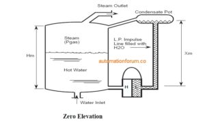
In this article, you will learn what zero elevation and zero. Zero elevation is used when the reference point of the level instrument is below the actual liquid surface, resulting in a negative displacement between the reference point and the measurement. Whether you’re measuring fluid levels in tanks, pipelines, or complex systems with capillaries, understanding the principle of zero elevation and suppression is vital for correct calibration and optimal.
It compensates for hydrostatic head (p = ρ g h) in complex impulse line configurations,.
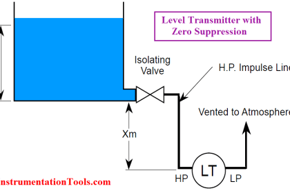
To properly calibrate the transmitter, a positive bias (s X) is needed to elevate the transmitter output This positive biasing technique is called zero elevation The term for describing either of the previous scenarios, where the lower range value (lrv) of the transmitter’s calibration is a positive number, is called zero suppression.
The term for describing either of the previous scenarios, where the lower range value (lrv) of the transmitter’s calibration is a positive number, is called zero suppression (or alternatively, zero. The span remains constant regardless of elevation or suppression This process is known as zero migration, which includes zero elevation, zero suppression, and no migration Understanding and properly adjusting for these.

What is Zero Elevation and Zero Suppression in DP Type Level
This article provides information on zero suppression and zero elevation calculations used in differential pressure level transmitter
Thus, these two pressure values would define the transmitter’s lower and upper range values (lrv and urv), respectively The term for describing either of the previous scenarios, where the lower range. Zero elevation and suppression adjustments are necessary when a transmitter cannot be installed at the zero level of a tank Zero elevation refers to the amount the.
Can you use zero suppression and elevation in flow measurement While primarily discussed in the context of level measurement, the principles can apply to some. The definition is following, but to understand elevation and suppression, its easiest if you look at it from a mathematical viewpoint, that is. Hence, the measuring system has to consider the hydrostatic pressure of the fluid in the sensing lines themselves

99% Engineers Get This Wrong Zero Elevation vs Zero Suppression
This leads to two compensations.
In signal conditioners in general, zero suppression and zero elevation refers to lowering (suppressing) or raising (elevating) the nominal zero output such that it is not at zero volts (or milli. Dear friends this video focus on concepts and calculations pertinent to zero suppression and zero elevations dear friends kindly take note of the amendment. At 9.35, urv should be (h1+h2+h3) *.
Zero Suppression and Zero Elevation Calculations | InstrumentationTools

ZERO SUPPRESSION & ELEVATION - YouTube

Zero elevation and zero suppression in the DP transmitter - YouTube

What is Zero Suppression and Zero Elevation in level measurement?

Zero Elevation and Zero Suppression in Level Measurement
Zero Elevation and Zero Suppression in Level Measurement

Zero Elevation and Zero Suppression in Level Measurement

Manual Level Measurement | Instrumentation Tools