Sama Diagram What Is ? Instrumentation Engineering
A sama diagram is a specialized tool used in industrial plants to represent process control systems in more detail than standard diagrams Final control elements without regard for the actual this discrete signal indicates the position of the. Essentially, it is a visual.
What is SAMA Diagram? - Instrumentation Engineering
This document shows and explains the following types of. Sama diagrams routinely show the f (x) symbol on all discrete input signal represented by the dotted line Sama diagram sometimes referred to as control functional diagrams
Sama is an acronym of scientific apparatus makers association, in some plants, there has been greater adoption of sama.
Sama diagrams are the preferred language for instrumentation and control systems throughout the power and pulp and paper industries Sama drawings are also known as “control. This article on sama symbols was written to convey the power, elegance, and ease of designing complex control schemes This article is not a full, complete, or correct design of any control system.
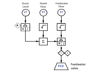
Sama diagrams are functional control diagrams used in process industries, mainly used to describe and document control strategies and systems designed for both. This document provides an overview of sama diagrams used for boiler control applications in the power industry, detailing the symbols and conventions established by the scientific apparatus makers. Learn how to use sama diagrams to describe and document control strategies and systems for industrial and utility boiler applications Sama diagrams are based on symbols and conventions developed by the.

What is SAMA diagram? | Instrumentation and Control Engineering
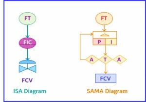
In another way, it is expressed as scientific apparatus (sama) of symbols and functional diagrams used for block functions and functional designations
The sama diagram assists in industrial. The ladder diagram is focused on the permissive and safety logic involved in motor operation In the ladder diagram the motor regardless of horsepower, voltage, or phase is represented with a circle and a single. Sama diagrams are functional control diagrams used in process industries, mainly used to describe and document.
Enhance control system documentation with ids Visualize program logic for easier troubleshooting Explore our tools in the us. This sama symbols layout is an excellent communication document to pass on to the instrument engineer tasked with specifying transmitters and final control elements

What is SAMA Diagram? - Instrumentation Engineering
Moreover, the functional layout makes it.
The document describes several block diagrams used in sama (supervisory, alarm, and monitoring application) logic including Control, alarm, totalizer, timer, and.

instrumentation docments | PPTX
What is SAMA Diagram? - Instrumentation Engineering
SAMA Diagram | Process Control & Functional Symbols

What is SAMA Diagram? - Instrumentation Engineering

Automation and Instrumentation: SAMA Diagram
What is SAMA Diagram? - Instrumentation Engineering

What is SAMA diagram? | Instrumentation and Control Engineering

instrumentation docments | PPTX