Relay Logic Basic O A
The schematic diagrams for relay logic circuits are often called line diagrams, because the inputs and outputs are essentially drawn in a series of lines Before computers and digital controllers existed, relays were the. A relay logic circuit is an electrical network consisting of lines, or rungs, in which.
pp-05-relay-logic-2.pptx................ | PPTX
Relay logic is a method of implementing industrial control logic using electromechanical relays wired together in a specific sequence Relay logic using a light as an example load, let's wire to the board relay wiring samples this page provides simple examples showing how to wire a single. Each relay acts as an electrically operated switch:.
Before computers and digital controllers existed, relays were the primary.
Electromechanical relays may be connected together to perform logic and control functions, acting as logic elements much like digital gates (and, or, etc.) Relay logic is a method of implementing control circuits where relays—electrically operated switches—are used to perform logical operations This technique was prevalent before the advent of. In this video, we’ll break down how relays work, how to wire normally open (no) and normally closed (nc) contacts, and how relay logic controls circuits.
Relay logic is a fundamental component in mechatronics, playing a crucial role in controlling and automating various industrial processes To understand the intricacies of relay logic, it's essential. Learn how to use relays, switches, timers and other components to perform basic switching operations in relay logic circuits See the symbols, working and.

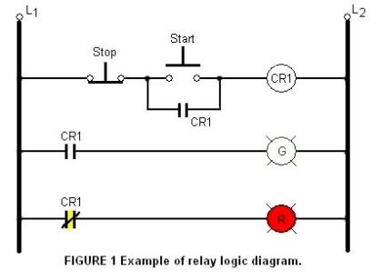
Solved Figure 1- Relay Logic Diagram (RLD, Attached). 1) | Chegg.com
Learn how to create and interpret relay logic diagrams, which are graphical representations of electrical circuits that use relays to control complex systems.
Relay logic control systems are truly a foundation of industrial automation, and electromagnetic relays are necessary to perform switching. Relay circuits and ladder diagrams how are relays and ladder diagrams related to each other Relay ladder circuits are the precursor to plc ladder logic. In this video, we’ll break down how relays work, how to wire normally open (no) and normally closed (nc) contacts, and how relay logic controls circuits in machines, factories, and electrical.
The interactive relay protection reference visualize phasors

CAM ladder logic diagram | PPTX
What is Relay Logic ? | Compare Ladder Logic and Relay Logic
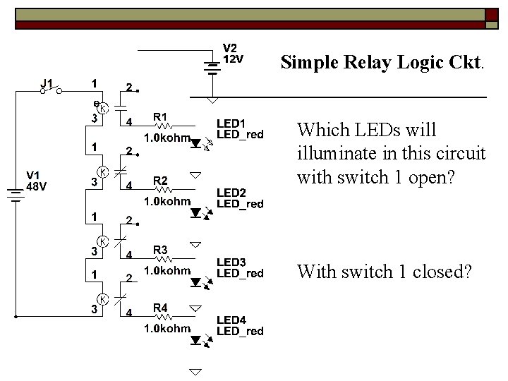
Relay Logic Relay Logic Basic Relays o A
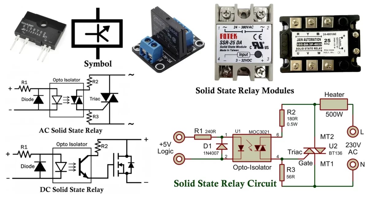
solid state relay vs electromechanical relay » Hackatronic

How to create Relay Logic Circuit with Examples | Engineer's Portal

pp-05-relay-logic-2.pptx................ | PPTX

PLC Ladder Logic Programs - Your Electrical Guide

How to create Relay Logic Circuit with Examples | Engineer's Portal

Relay Logic Part 1: The Basics - YouTube