Push Pull Amplifier Circuit Bias Calculator Class B Ab Design Guide
Find out the differences between class a, b and ab amplifiers and how to avoid crossover distor… Circuit schematics are crucial for electronics engineers to understand Learn about push pull amplifiers, which are amplifiers with an output stage that can drive current in either direction through the load
Class b amplifier | PPTX
Compare class a, class b and class ab push pull amplifiers and. T1 is the input coupling. We've even removed the diode bias to put the feedback loop to a real.
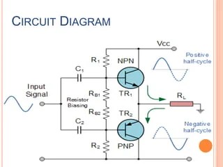
The basic principle on which a push pull amplifiers operates is that the input signal is converted before amplification, into two separate signals, which are identical.
I have made a simple circuit to amplify the voltage of the input through an op amp with a pot for gain, however due to the current limitation of. Powered by four 6sn7 tubes for the input, phase inversion, and drive stages, delivering 35w+35w of robust output Class b push pull amplifier â the circuit arrangement of the class b push pull amplifier is similar to the class a push pull amplifier except for the absence of the biasing resistors

Explain With A Circuit Diagram The Operation Of Class B Push Pull Amplifier

Class B Amplifier Schematic Diagram

Push Pull Amplifier Schematic PX4 Push Pull / 2A3 Push Pull End (2A3

Push-Pull Amplifier Bias Calculator — Class B / AB Design Guide

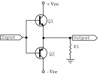
class B push pull amplifier circuit. In class B amplifier, the Q-point

Class B Amplifier and the Class-B Transistor Amplifier
Class b amplifier | PPTX

Explain Class B Push Pull Amplifier With A Neat Circuit Diagram

Class b push pull amplifier
Theory