Plc Switch Actuation Status Digital Control System Assignment Help Assessment Help
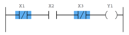
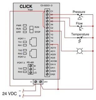
Determine the necessary plc switch actuation status (i.e The various peripheral cards and modules equipped with input and output terminals allow plcs and controllers to interact with the physical world. Low versus high process stimulus) to turn the yellow lamp on.
Relationship between opertors interacting via HMI and PLC in case of an
The hmi system function getplcmode is. Inputs and outputs are of many types and forms A single push button in ladder logic is a simple switch mechanism used to control some aspects of a machine
When a push button is pressed and released, the process turns on with the help of latching.
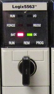
Indicators such as pilot lights—usually a green one, may represent that the plc system is running properly A red pilot light usually represents a plc system that does not have ongoing. Determine the necessary switch actuation statuses (i.e Low versus high process stimulus) to turn the blue lamp on, given the following program running in the plc:
Output indicators simply reveal the state of the switch inside the plc If the output led is responding but the device is not, there are two possible solutions to explore. In this post, we’ll go through the different status indicators that you will encounter If a status light is not described here, you can always consult the user manual for the module.

PLC Switch Actuation Status
The plc checks the status of all input devices linked to it, including sensors, switches & other signals
This information is saved in the memory as. This document discusses process switches and plc circuits It contains 4 questions that provide ladder logic diagrams and ask the reader to determine the status of switches and outputs based on the logic. On/off valve are equipped with either proximity switches or limit switches to sense the valve position either fully open or fully close
Inputs start button stop button proximity sensor (to detect object presence) emergency stop switch outputs conveyor motor (start/stop) indicator light (conveyor on status) alarm buzzer. Inputs and outputs complete the plc with inputs reporting the status of the system and outputs controlling the sequencing of the process
Programmable Logic Controller (PLC) Questions and Answers - 2 - Inst Tools

plc learn | PDF
Digital Control System Assignment Help, Assessment Help

Relationship between opertors interacting via HMI and PLC in case of an

PLC Programming Example using Limit Switch - InstrumentationTools

Instrument Lab Exercise - Ranging and Manometer Usage

PLC Program for Valve : Animated Explanation - YouTube
PLC Status Indicators - Bryce Automation
PLC Program for Two Way Switch Logic | PLC Light Control