Interlocking Three Inputs For Pump Logic Understanding The Basics Of Interlock Diagrams A Comprehensive Guide
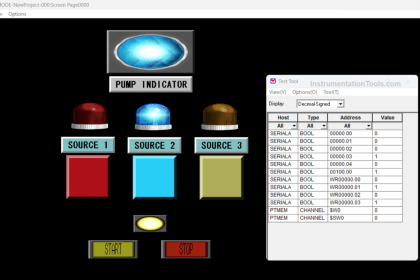
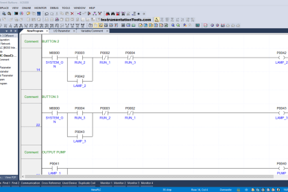
This article explains the application of the latching and interlock concepts in plc programming to control a pump using three different buttons. The “reverse command” tag (normally closed) in series after the “forward (cw) button” is for the interlocking mechanism Using siemens tia portal, engineers can implement robust pump logic that combines latching and interlocking
PLC Ladder Logic for Three Motors drive Simultaneously with
A maximum of three types of interlock can be used depending on the block Learn ladder logic programming for pump control using siemens tia portal Three separate inputs named permit, intlock and protect are available for these functions.
To configure the interlocking of three inputs, we need to ensure that the pump activates only when all three inputs are closed
We will use the and contact. You can do exactly that in the free. This article discusses the implementation of the latching and interlock concepts in a plc program for controlling a pump with 3 different. The application example describes the creation and visualization of interlocking using the pcs 7 logic matrix

PLC Ladder Logic for Three Motors drive Simultaneously with
Concept of Interlocking in PLC - Interlock Ladder Diagram

How to Create a P&ID

Understanding the Basics of Interlock Logic Diagrams: A Comprehensive Guide

PLC Ladder Logic for Three Motors drive Simultaneously with

Structured Text PLC Example for Motor Interlocking and Control

Interlocking in PLC – Interlock Logic, Working & Wiring Example

Three Motor Interlocking Diagram | Engineers CommonRoom - YouTube
DCS - Distributed Control System

plc programming latch unlatch and interlocking pump logic in Zelio soft