Instrument Loop Diagram Open And Close How To Read I L
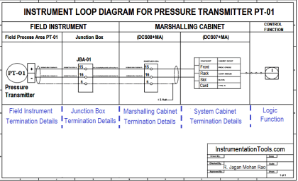
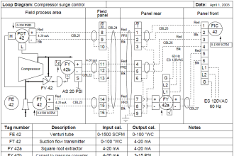
Instrument loop diagram (ild) represents a connection from field instrument to junction box, marshalling cabinet and system cabinet for a plc or dcs. When a loop diagram shows you exactly what wire color to expect at exactly what point in an instrumentation system, and exactly what terminal that. Learn what instrument loop diagrams (ilds) are, how to make them, and how to read them
Load Cell Working Principle - Inst Tools
Find out the sources, symbols, and examples of different types of ilds for process. A loop diagram is a schematic representation that illustrates how an instrument loop functions —from field devices to the control system and back. Learn what instrument loop diagrams are, how they differ from p&ids, and what information they contain
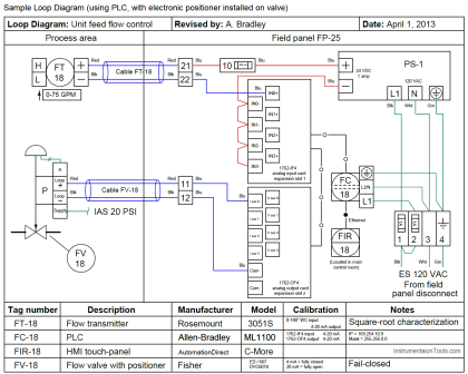
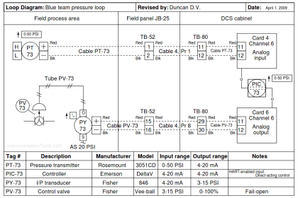
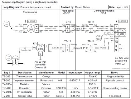
See an example of a loop diagram with instrument bubbles, wires, terminals, calibrations,.
Instrument loop diagrams (ilds), sometimes called loop drawings, are critical engineering documents that define how instrumentation and control systems are connected, monitored, and operated in. Learn how to create and use loop diagrams and process loop sheets for instrumentation and control systems These drawings show the wiring details of devices, equipment, and process data. Learn how to draw and read process and instrument diagrams (p&ids) and loop diagrams that show the flow and control of the process
See examples, symbols, tagging and. What is a loop diagram
How-to Create Instrument loop diagram? | Marshalling Loop Diagrams
Instrumentation Loop Diagrams - InstrumentationTools
Load Cell Working Principle - Inst Tools

Open and Close loop Diagram / Instrument Loop Diagram / How to Read I.L
Instrumentation Loop Diagrams - InstrumentationTools

Instrument Loop Diagram Example

Understanding Loop Diagrams and Process Loop Sheets

Instrument Loop Diagram (Part - 12G) - YouTube
Purpose of Loop Diagrams - Instrumentation Design
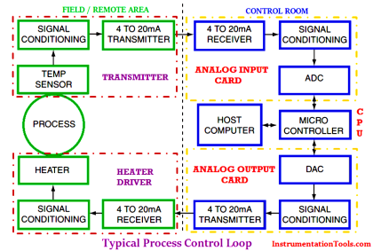
How Process Control Loop Works | Instrumentation Tools