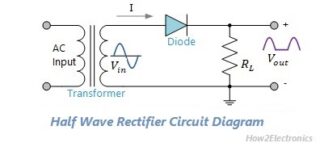
Half Wave Rectifier Circuit Diagram Form Formula & Applications
A rectifier is a device that converts alternating current (ac) to direct current (dc) This post includes its theory, working & ripple factor and center tapped full wave rectifier. It is done by using a diode or a group of diodes
Draw A Circuit Diagram Of Half Wave Rectifier - Circuit Diagram
Half wave rectifiers use one diode, while a full wave rectifieruses multiple diodes Full wave rectifier rectifies the full cycle in the waveform The working of a half wav…
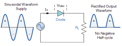
It does this by allowing the ac signal to pass only during.
The half wave rectifier circuit operates by using a diode to prevent one half of an alternating current waveform to pass As a result only part (typically half) of the. In this video, we will learn about the half wave rectifier in a simple and practical way A half wave rectifier is an electronic circuit that converts ac vol.
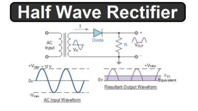
A half wave rectifier is one of the basic circuits that performs this conversion and helps us learn the fundamentals of power supply circuits This article provides insights into the half wave rectifier, its. Learn how a half wave rectifier circuit transforms ac voltage to dc voltage using only one diode Find out the ripple factor, efficiency, form factor and applications.

Rectifier Circuit Diagram What Is A Rectifier? Types Of Rectifiers And
In a half wave rectifier, the input sine wave is 200sin200 ᴨt volts
If load resistance is of 1k then the average dc power output of half wave rectifier is __________ Bridge rectifier a bridge rectifier is an electrical circuit that converts alternating current (ac) into direct current (dc) It is classified as a full wave rectifier circuit. In a rectifier circuit, diodes are arranged in such a way that they only allow current to flow in the desired direction only
In its simplest form, a rectifier circuit can consist. Many electronic circuits require a rectified dc power supply to power various electronic basic components from the available ac mains supply
Half Wave Rectifier Basics, Circuit, Working & Applications

Circuit Diagram Half Wave Rectifier Wave Half Rectifier Waveform
Half Wave Rectifier: Circuit, Diagram, Waveform, Formula & Applications

Half and Full Wave Rectifier Working Principle | Circuit Diagram

Draw A Circuit Diagram Of Half Wave Rectifier - Circuit Diagram

What are Half-Wave Rectifiers? Definition, Circuit and Working of Half

My PCB Layout

Half Wave And Full Rectifier Circuits With Without Filter
Half Wave Rectifier Basics, Circuit, Working & Applications