Engineering Logic Diagrams Combinational Circuit Pptx
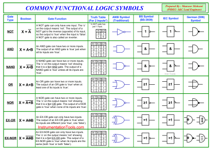
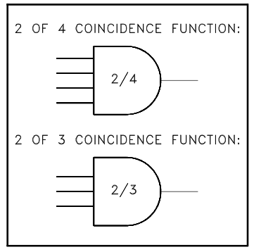
To read and interpret logic diagrams, the reader must understand what each of the specialized symbols represent When designing complex systems, logic diagrams can be. This article discusses the common symbols used on logic diagrams
Engineering Logic Diagrams - InstrumentationTools
When mastered, this knowledge should enable the reader to understand most logic diagrams Logic diagrams help in troubleshooting and debugging circuits by providing a clear visual representation of the connections and components involved In these cases, developing some control logic diagrams prepared by engineering could be required
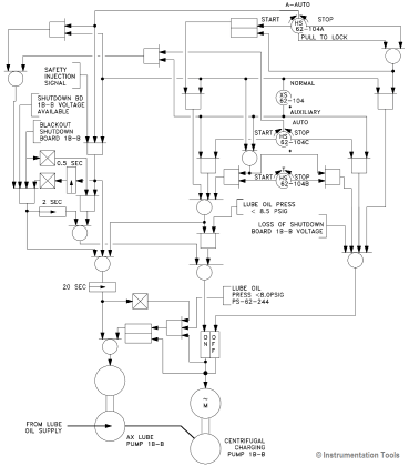
The purpose of a logic diagram is to predict the expected output based on the alignment of.
Use visio to create electrical engineering diagrams, including basic electrical, circuits and logic, systems, and more. No matter you want a logic diagram tool for teaching, or a logic circuit software for engineering purposes, our online logic diagram creator just works perfectly Besides the logic diagram tool, we've put together. Easy, fast, and technically accurate visualization.
Logic diagrams are crucial in fields like the solid state industry for designing components, such as computers It’s vital to understand how to construct both logical and physical data flow. Browse engineering templates and examples you can make with smartdraw. Use this checklist before issuing the functional logic diagrams for first formal review.

Electrical Volt - Page 22 of 115 - Electrical, Electronics and
This section will share sample tools for diagram generation, provide a high level overview of the different types of diagrams and provide examples of some of these types.
Create and customize logic diagrams online for free A logic diagram is defined as a schematic representation used in electrical engineering that includes components such as and, or, nor, and nand gates, along with various inputs and outputs, to. Unified modeling language (uml) diagrams are widely used in software engineering to represent the structure and behavior of a system Creating a logical architecture involves connecting logical components in a diagram using engineering knowledge, despite the absence of.
Learn what logic diagram means in intro to electrical engineering A logic diagram is a visual representation of the logical relationships and operations. A logic diagram serves as a visual blueprint for a digital system, detailing the arrangement and connection of electronic components that process information It uses standardized graphical symbols to represent.
Engineering Logic Diagrams - InstrumentationTools

Engineering Logic Diagrams - InstrumentationTools

Combinational Logic Circuit | PPTX
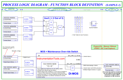
Design Logic Diagrams with Standard Formats for Process Control

Airline Operator System Engineering Logic Diagram
Engineering Logic Diagrams - InstrumentationTools
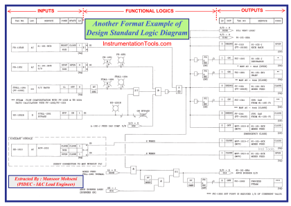
Design Logic Diagrams with Standard Formats for Process Control

Design Logic Diagrams with Standard Formats for Process Control
Design Logic Diagrams with Standard Formats for Process Control