Clamper Circuit Positive Negative And Biased
What is a clamper circuit A clamper circuit is an electronic circuit that adds or subtracts a constant dc voltage to an ac signal, ensuring the entire waveform shifts vertically without. A clamper circuit, or clamping circuit, fixes the positive or negative peak values of a signal to a defined level by adjusting the.
Clamper circuits - Positive clamper, Negative clamper and Biased clamper
Clamper circuits are essential in electronic circuits because they allow signals to be changed in voltage levels without altering the shape of their waveforms This article explains clamper circuits from the ground up including their types, mathematical analysis, waveforms, working principle, differences,. These circuits are used in.
Learn how to design and use a clamper circuit to add a dc shift to an ac signal without distorting its shape
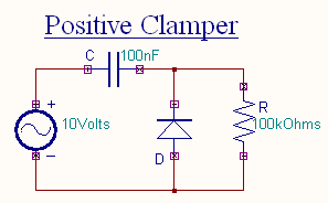
A clamper circuit can be defined as the circuit that consists of a diode, a resistor and a capacitor that shifts the waveform to a desired dc level without changing the actual appearance of the applied signal. Learn about diode clippers and clampers, circuits that modify input signals to fit the operating range of electronic devices A clamper is an electronic circuit that changes the dc level of a signal to the desired level without changing the shape of the applied signal In other words, the clamper circuit moves the whole signal up.
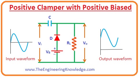
A clamper circuit (also called a dc restorer or level shifter) is an electronic circuit that shifts an ac signal to a different dc. Learn what clamper circuits are, how they work, and how they shift the dc level of ac signals Explore the types of clamper circuits, such as positive, negative, and biased clampers, and their waveforms and. Read about clamper circuits (diodes and rectifiers ) in our free electronics textbook

Clamper circuits - Positive clamper, Negative clamper and Biased clamper
Diode clamping circuit a diode clamping circuit is basically a wave shaping circuit that uses a single diode, a capacitor and a resistor to shift an entire signal.
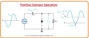
An electronic circuit that is used to alter the positive peak or negative peak of the input signal to a definite value by shifting the entire signal up or down to obtain. A clamper is an electronic circuit that produces an output, which is similar to the input but with a shift in the dc level In other words, the output of a clamper is an exact replica of the input.

Clamper Circuit: What is it? (Diode & Voltage Clamping Circuit

What are Clamper Circuits? Definition, operating principle

Clamper circuits - Positive clamper, Negative clamper and Biased clamper
Tech Lab: Study of diode as a Clipper & clamper Circuit

Clamper circuits - Positive clamper, Negative clamper and Biased clamper
Diode Clamper Circuits - The Engineering Knowledge
Diode Clamper Circuits - The Engineering Knowledge

Applications of Diodes: Clipper and Clamper Circuits

Clamping Circuit | Negative and Positive Voltage Clamping Circuits