Bridge Full Wave Rectifier Operation Basics Circuit Working & Applications
The blue plot on the waveform shows the result of using a 5.0uf smoothing capacitor across the rectifiers output A bridge rectifier is a versatile rectification circuit composed of four diodes arranged in a bridge configuration Previously the load voltage followed the rectified output waveform down to zero volts
Electrical Standards: Full wave rectifier; Full wave bridge rectifier
Here the 5uf capacitor is charged to the peak voltage o… Fig 19 dual supply full wave bridge rectifier operation in negative half cycle when a negative half cycle is introduced to bridge rectifier d1 and d3. A simple explanation of bridge rectifiers
Learn what a bridge rectifier is, the working principle & operation of a bridge wave rectifier, and its circuit diagram.
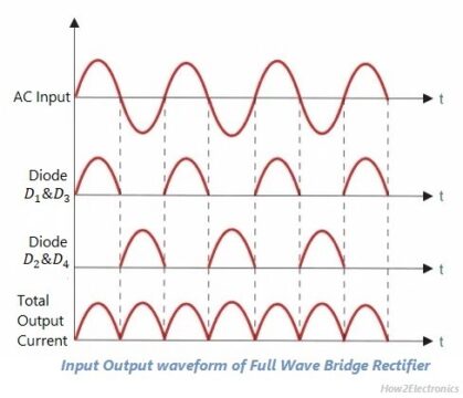
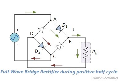
In full wave bridge rectifier, an ordinary transformer is used in place of a center tapped transformer The circuit form a bridge connecting the four diodes d1, d2, d3 and d4. This article explains how a full wave bridge rectifier works, its circuit diagram and output waveform, key design formulas, efficiency limits, and. Here we will discuss what is full wave bridge rectifier, working principle, circuit diagram, waveforms, formula, advantages, and disadvantage.
The secondary winding of the transformer is connected on one. Learn about the operation of this essential circuit. Only two of the four diodes, designated d1 through d4, carry current throughout each half cycle,. In this video we look at the full wave bridge rectifier, the half wave rectifier the full wave rectifier, center tapped transformers, diodes, load, oscilloscope.

Bridge Full Wave Rectifier Circuit Diagram
This electronics video provides a basic introduction into full wave rectifiers which converts a sine wave ac signal into a pulsating dc signal using two diodes, a load resistor, and a center tap.
Full Wave Rectifier Basics, Circuit, Working & Applications

Full Wave Bridge Rectifier with Capacitor Filter Design | Diagram of a
Full Wave Rectifier Basics, Circuit, Working & Applications

Full Wave Rectifier : Circuit Diagram, Types, Working & Its Applications

Electrical Standards: Full wave rectifier; Full wave bridge rectifier

Full Wave Bridge Rectifier – Circuit Diagram and Working Principle

Bridge rectifier

Full Wave Rectifier-Bridge Rectifier-Circuit Diagram with Design & Theory

Full Wave Bridge Rectifier Animation